Mating the Motor to the Transaxle
Mating the Motor to the Transaxle
Designing the Adapters
The process of installing the new electric motor in place of the original internal combustion engine has been by far the most time consuming part of the project. Precisely aligning the shaft of the electric motor to the driveline of the existing vehicle required the design and fabrication of custom parts with tight tolerances. Since I don't have the tools or skills to fabricate these, I did the design and had a local machinist do the fabrication. The difficulty is in finding someone with the necessary skills that is willing to do a one-of-a-kind build. Many machine shops prefer to do higher volume machining. Fortunately I found Ames Mechanical Development, a one-man machine shop in Stillwater, MN.
Before starting fabrication I needed to create the design. There are three parts involved and the exact locations and tolerances of the machined features will allow the EV to drive smoothly and silently. I've read horror stories of other EV converters who've spent a lot of time and money making the adapter parts only to have the vehicle vibrate when going down the road.
The three parts I designed and had fabricated are:
It should be noted that for this particular transmission there is no pilot shaft or bearing that supports or aligns the transaxle shaft at the motor end. Many transmissions have such a feature, which I believe would make alignment easier. However, the Ford Focus MTX75 transaxle shaft simply ends after the splines that engage the clutch.
In the measurement and machining of the adapter parts I tried to hold the critical dimensions so that the alignment of one shaft to the other is within 1 thousandth of an inch, although in reality it is probably not quite that close. We'll see whether I achieved a tight enough alignment when I get it on the road.
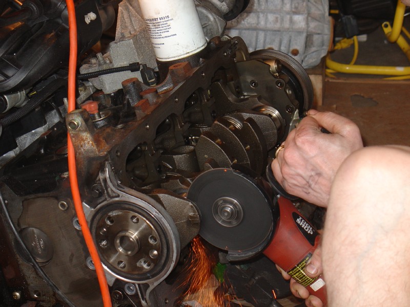
I started with the design of the flywheel hub. I began by cutting off the end of the crankshaft from the original engine, hoping to modify this for my use. There's no chance that thing is ever going to spew greenhouse gasses again! Cutting the end off the crankshaft
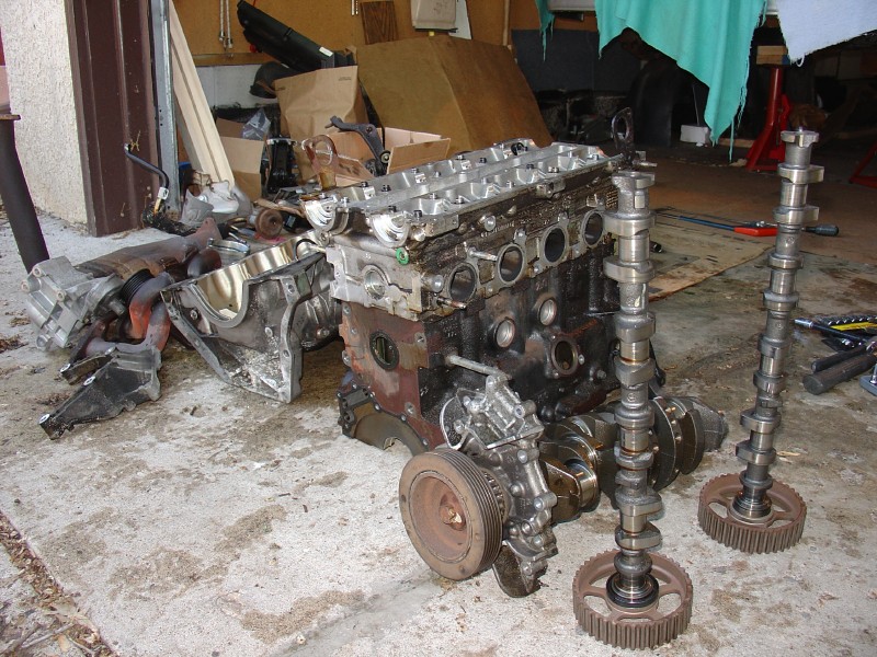
Here's what's left of the engine after removal and disassembly. Just a pile of srcap at this point. The engine in pieces
After cutting off the crankshaft end I found that there's not enough material behind the outer face to allow me to adapt it to the electric motor. The connection to the motor shaft uses a QD bushing, which has a taper that locks the flywheel hub to the shaft. The crankshaft end wasn't large enough to machine a tapered hole for the bushing and leave a thick enough wall to provide adequate strength. So I designed a new flywheel hub from scratch to match the specific tapered bushing that I chose. I bought the bushing and took it to the machinist along with the drawing so that he could precisely match the diameter and depth of the taper. The 2D CAD drawing can be found in a PDF files below.
CAD Drawing - Flywheel Hub sheet 1 (PDF file)
CAD Drawing - Flywheel Hub sheet 2 (PDF file)
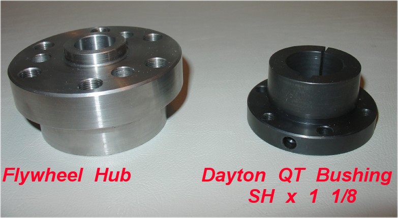
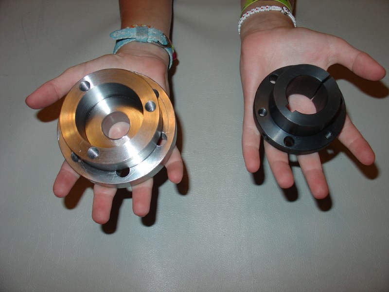
Here's the flywheel hub after fabrication alongside the QD bushing. Flywheel Hub and Bushing picture
And another view with my 9 year-old daughter's hands for scale. Flywheel Hub and Bushing picture - another view
This flywheel hub is made of 4340 steel (higher yield strength than the prototype version made from 8620 steel.) This design can be used to adapt an ADC 9" motor with a 1 1/8 inch shaft to the flywheel from a Ford 5-speed MTX75 transaxle, which is used in the Focus (with a Zetec engine) and the Contour. It requires the use of a Dayton QD Bushing. (SH series, 1 1/8 inch bore. Available at www.grainger.com, part number 4JU46, around $14)
While the hub was being fabricated I took the transaxle to the quality control department of a machine shop where precise measurements could be made. The QC guy measured the critical features on the mating face of the transaxle. I made the mistake of not being present when he did this, and I later found by running some trigonometry calculations on the measurements that he had not used the transaxle shaft as the reference. Instead he had used bearing surface near the shaft, which is not the critical alignment feature. As a result the time and money spent on this measurement were wasted. I started over with another QC guy who runs his own business just doing component physical measurements. (Mic-Right Inspection Services) This time I sat down with him while he calibrated, ran, and re-ran his CMM machine. (A very expensive, air-suspended, computer-controlled measurement machine.) This time I got the measurements I needed.
Using these measurements and the drawing of the electric motor I created 2D drawings of the adapter plate and the motor spacer. The drawings can be found in PDF files below.
CAD Drawing - Adapter Plate drawing sheet 1 (PDF file)
CAD Drawing - Adapter Plate drawing sheet 2 (PDF file)
CAD Drawing - Motor Spacer (PDF file)
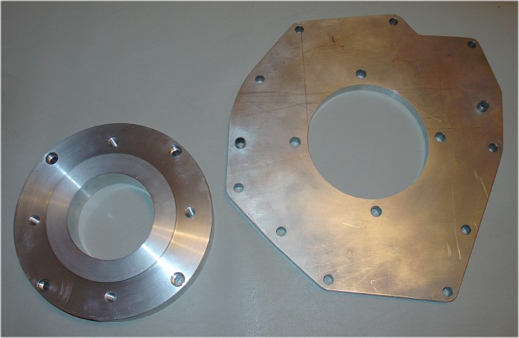
The adapter plate and the motor spacer are made from 6061 Aluminum. Adapter Plate and Motor Spacer picture
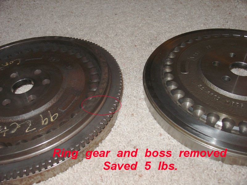
While the parts were being fabricated I went to work on the flywheel. I lightened it by removing the ring gear (a propane torch and a few good whacks with a hammer.) I also had the machinist remove the boss that held the ring gear, since it was no longer needed and this weight is at the outer diameter where rotating inertia is greatest. Next I had the flywheel surfaced at an engine shop that builds racing engines, and had them balance the flywheel and pressure plate together.
Assembly of the Flywheel, Clutch, and Pressure Plate
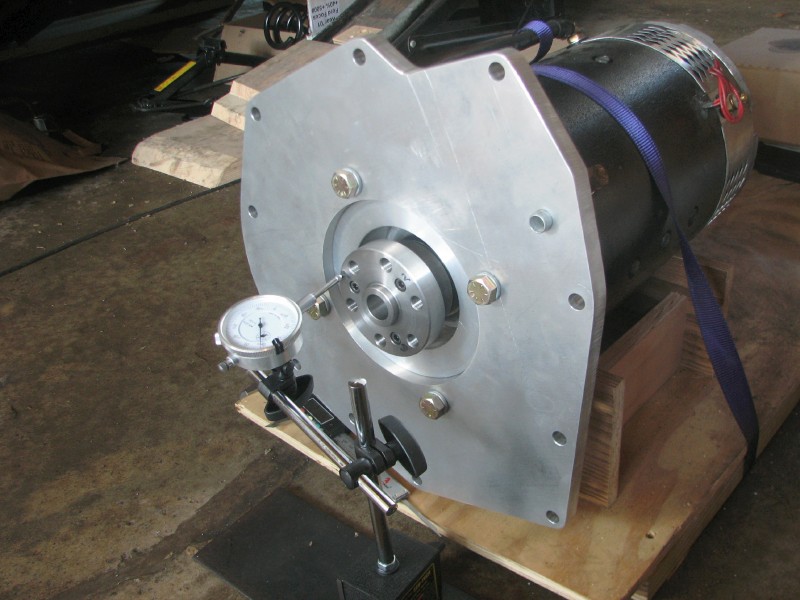
Once all of the parts were fabricated I bought 1/4-20 hex head screws, 1/2-13 Bolts (grade 8), 1/2" lock washers, and put it all together. I followed the instructions that Electro-Auto provides with their adapter kits. Before tightening the 1/4-20 screws in the bushing I slid the hub on the shaft until the flywheel mounting surface was located the same distance from the transaxle mounting face as it was with the original engine. The bushing screws were then torqued using values from the bushing manufacturer. No locktite or lubricants of any kind were used here. I used a dial-indicator to make sure that things were running true as I tightened the screws on the tapered bushing a little at a time.
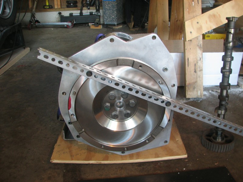
Checking runout to within 1 mil
I bolted the flywheel to the hub and torqued the bolts using values from the shop manual. I used blue locktite on the flywheel bolts.
Brace for tightening flywheel bolts
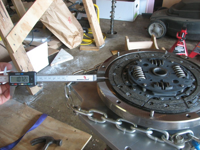
Next I stood the motor on-end with the flywheel facing upwards and aligned the clutch disc on the flywheel using calipers to get it centered (since I didn't have a clutch pilot tool.)
The pressure plate was bolted onto the flywheel, again using blue locktite and torque specifications from the shop manual. At this point it was ready to put in the car.
Installing the Motor
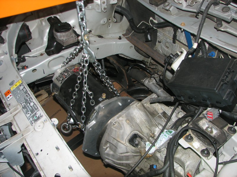
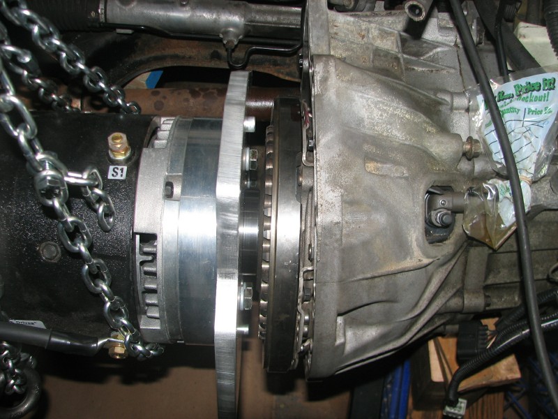
I was working on installation of the motor on my day off work and didn't have anyone else around to give me a hand. Using the engine lift and chains I was able to position the motor in line with the transaxle that was already installed in the car. I made sure that the motor was perfectly level and lowered it into the car, in the same position previously occupied but the gas engine. To my surprise the shaft and the dowels lined up and I was able to mate them with little effort.
Aligning the motor to the transaxle
My cost for the three custom machined parts was $1,100. This is more than I had wanted to spend and I could probably get it done cheaper if I created true CAD files that allowed it to be done on a CNC machine. Since I don't have a 3D CAD package I haven't taken this step.
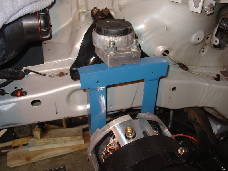
To finish the installation I had to create a mount for the end of the electric motor opposite the transaxle. This was pretty straightforward as I used the existing hydraulic motor mount, and the electric motor has mounting holes in the housing at that end. I used 1/8 inch thick angle iron and created a support bracket, being careful to level the electric motor before tightening everything. Support bracket (blue) connected to existing motor mount (grey with block on top)
Making the Drive Axle Bracket
The next step was creating a bracket to support the right side drive-axle bearing. Since this drive-axle shaft is longer than the one on the other side it needs to be supported in the middle near the inner CV joint. In the original car a heavy bearing bracket was bolted to the crankcase of the engine to support the bearing. I saved this original bracket but found that it doesn't fit with the electric motor in place. After considering fabrication of a new piece a co-worker suggested hacking up the existing bearing bracket and adding support braces. We figured out a way to do this and I bolted the modified support bracket to a split circular motor mount that clamps around the electric motor. In this way the drive axle is rigidly attached to the driving motor, just as it was with the original engine.
Here are some pictures of the steps used to modify and mount the bearing bracket. These are probably only interesting if you're planning to convert the same or a similar car.
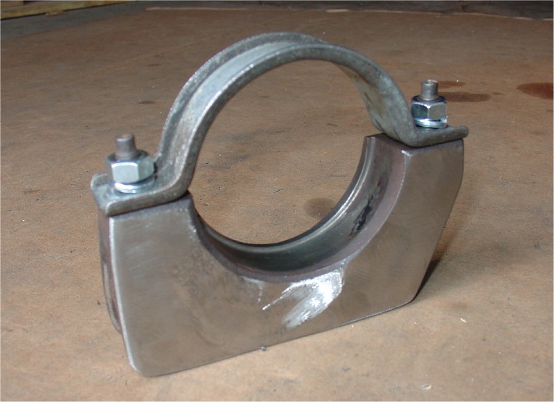
First the existing bracket was cut up and an angle grinder was used to make the sides flat. Original bracket after cutting
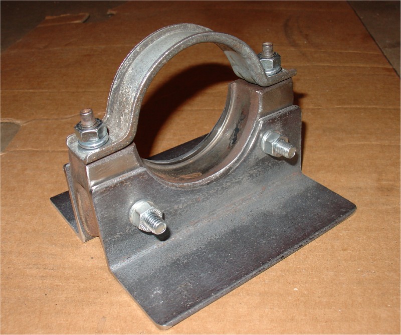
Next, angle iron braces were cut and drilled, then bolted through the existing bracket. A press was used to spread the angles a bit and create a flat mounting surface on the bottom. Bracket with angle iron attached
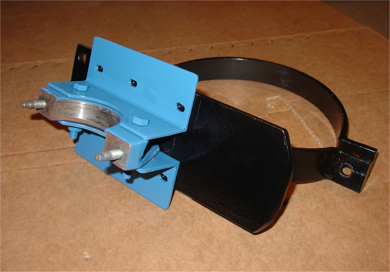
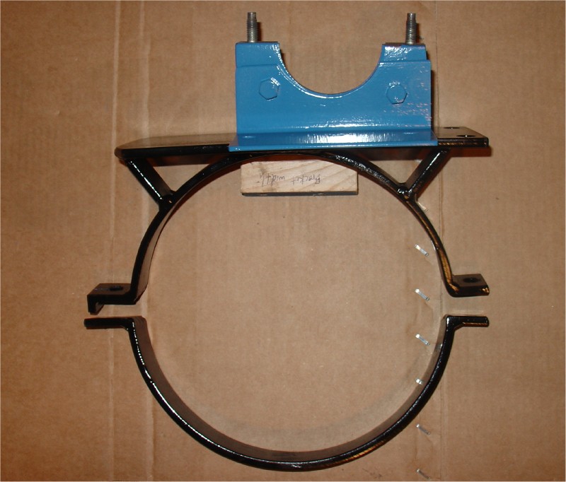
Finally, slots were drilled in the angle iron and holes were drilled and threaded (1/4 - 28) in the black circular motor mount. Six screws hold the bracket in place. The slots will allow adjustment of the bearing support while it is being assembled. Bracket after slotting and painting
The circular motor mount was purchased from KTA Services specifically for the 9" motor. I had planned to use it to support the motor, but since I found a better method using the existing hydraulic motor mount, the split circular piece found a new purpose. Bracket in position on the split circular motor mount.
I slid the new bearing bracket between the bearing and the motor, then put the circular motor mount in place around the motor in line with the bearing. By riotating the slpit motor mount and using the slots in the blue axle bracket I adjusted the position so that the drive axle is aligned with the centerline of the motor. (I did this by feel since precise measurements were difficult.) Then I tightened everything up and got ready to test the driveline.
Testing the Motor
The true test of the motor mount came when I connected a battery and let it run. Success! It rotates in the correct direction and, other than a bit of drag from the rusted brake rotors, runs smoothly.
Updated 16AUG2008 CHS