Upgrading to Lithium Batteries
After more than three years of driving, the original lead-acid batteries were losing capacity, with a corresponding reduction of range. I decided to take the plunge and invest in Lithium based batteries. I went in on a combined order with 4 other EV converters, and we together bought over $40,000 worth of GBS 100 A-Hr cells. We purchased these from Elite Power Solutions at a pretty good discount, due to the volume buy. (We paid $115 per cell, plus a small amount for shipping.)
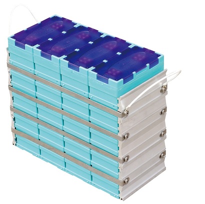
The cells we bought are based on LiFeMnPO4 chemistry. The part number for the pack of 4 cells is GBS-LFMP100AH, and it looks like this:
I purchased 88 Lithium cells, and will use them as two parallel strings with 44 cells in each. This is the maximum number of cells that will fit the existing battery boxes, and will provide over twice the range of the lead-acid batteries, with a total battery pack weight around 1/2 of the lead-acid batteries.
I had initially planned to connect the two parallel strings of batteries using fuses across the two; from each cell in the first string to the corresponding cell in the other string. This approach would allow a single BMS sense board to monitor the cells in each string. After a few discussions with others I came to the conclusion that for any imbalance between the two strings, the fuses would all burn out and I would be left with two parallel, isolated strings.
So after a bit of research and discussions with several other EV converters, I have decided to connect the cells in 2 parallel strings that are tied together at the top and bottom, but isolated everywhere in between. Somewhere in the middle of each string (I chose the middle) there is a series diode, so that current cannot flow backward from one string into the other when one string has one or more bad cells. This approach doesn't work for a car with regenerative braking, since current must flow back into the batteries during normal driving, but works fine for the FocusEV which has a DC motor without regen.
I decided to use a single charger to charge the entire pack, rather than splitting the pack into top and bottom halves with two chargers as I had done with the lead-acid pack. This works out better for using a BMS that monitors and displays many differnet parameters about the state of the battery pack I'll be using an Elcon PFC-3000 charger, which delivers slightly higher power than my previous arrangement with two chargers. I'll run the charger on 230 VAC outlet rather than two 115 VAC circuits.
I also decided that I'll install a battery management system (BMS) with a sense board on each individual cell. This approach, in my opinion, provides the best protection against overcharging a cell, and reduces the probability of a fire for the case of a catastrophic cell failure. It also means that I'll be able to monitor the voltage and temperature of each cell as I drive. I plan to eventually connect the BMS to a small computer (through a CAN bus) to be able to calculate and display useful information about state of charge, instantaneous power, battery balance, and energy efficiency.
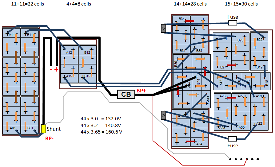
The diagram for my two parallel strings is shown below. (The wires at the top and bottom of the figure to the left of the contactors will connect to the controller and motor.)

Below is a diagram of how the cells fit into the 4 battery boxes that are in the FocusEV.
It turns out that it is a tight fit to get the 88 cells in my existing battery boxes. Some of the packs of 4 cells had to be taken apart and re-assembled into packs of 3 or 6 cells. This meant fabricating new side straps, which hold the cells under compression to prevent swelling during charging and discharging. For shortend packs (3 cells each) I was able to cut down existing straps, bend them at a reduced length, drill new holes, and re-assemble the packs. For the new assembly with 6 cells I had to fabricate new straps from scratch. This proved to be a bit more time consuming than I planned since I used a 20 gauge stainless steel sheet. I was able to cut the sheet into thin strips, then built a fixture of precisely the right length to bend the ends. (Maintaining a tight tolerance on this dimension ensures that proper pressure is applied to minimize swelling.)
The next step was to create new cables to connect up the pack. Elite Power solutions provided jumpers that make this very easy when cells are placed end-to-end, but since my batteries are distributed in 4 different battery boxes, it required quite a few cables to connect all of the cells in two strings.
When I'm done I'll have a 140 VDC battery pack with 200 A-Hrs theoretical. Assuming that the maximum useable capacity is about 75% of theoretical, I'll be able to use 150 A-Hrs, which is a total energy of 21 KW-Hrs. Assuming a driving efficiency of 350 Watt-Hours per mile from the battery pack (this is a reasonable expectation based on data with the lead-acid pack) the car will have a real-world range of about 60 miles.
Elite Power Solutions indicated that the cells need to charge to a maximum voltage between 3.60V and 3.65V per cell, with the BMS balancer (optionally) beginning to shunt current at about 3.55V. He also stated that there's no reason to go above 3.65V per cell, since it won't add much energy, and battery lifetime is improved if they are not overcharged.
Updated 06JUL2012