FocusEV Instrumentation
Getting the car on the road was one thing, but getting everything to work properly takes a bit more time. Two items that I finally finished are the tachometer and the speedometer. The tachometer allows me to run the electric motor at peak efficiency, and to avoid overspeed conditions. The speedometer helps me operate the vehicle within the traffic laws!
I'm using the existing instrument cluster but it has taken some extra steps to get it working. When I removed the engine and associated sensors from the car I wasn't too concerned with keeping the control computer happy. The control computer (also called the powertrain control module or PCM) continuously monitors many sensor inputs and controls the engine and fuel systems. Examples of PCM input signals that have been removed include the crankshaft position sensor, oxygen sensor, mass airflow sensor, camshaft position sensor, and throttle position sensor.
On the first day that I drove the car as an EV I found that the speedometer and tachometer were not working. Hmmmm, maybe I should have paid more attention to all of those sensors. I traced through the wiring diagrams and found that the PCM receives various signals from the engine, then sends engine RPM, vehicle speed, and other data over a digital data bus to a microprocessor inside the instrument cluster. (This is the same data bus that one can access using an electronic auto scanner - the OBDII interface.) The trick is that the PCM must check some of the sensor inputs compared to others before determining that everything is OK and sending the data. In my case, everything isn't OK since most of he sensors are missing!
The instrument cluster microprocessor controls the various dashboard warning lights and the tachometer and speedometer gauges. The gauges are driven by what appears to be a 4-wire analog interface, but I don't have any information on how they work and an internet search turned up no data on the IC that drives them. I suspect this was a custom IC made just for Ford, so datasheets won't show up on commercial websites. So to use the stock gauges I need to feed the PCM with appropriate signals to allow it to send valid tachometer and vehicle speed data to the instrument cluster.
I began by checking the Vehicle Speed Sensor (VSS) that is installed in the transaxle. This sensor produces a signal with a frequency which is proportional to vehicle speed. (Some quantity of pulses pre mile.) Since this sensor was still present in the car I traced the signal to the PCM, connected an oscilloscope to it, and found that it was functional. (I did this in the garage with the front drive wheels up in the air.) One might assume that if this sensor is sending pulses, then the speedometer would work. But one would be incorrect; the signal was working just fine but the speedometer needle stayed at 0 MPH no matter the vehicle speed.
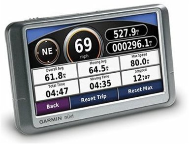
At this point I realized that this was going to take a while, so I bought a Garmin GPS (Nuvi 250) from www.newegg.com so that I'd have a way to display vehicle speed while I worked all of this out.
Just to see what data was being transmitted from the PCM to the instrument cluster microprocessor, I borrowed an auto scanner and connected to the OBDII test port. Just as I guessed the scanner reported many sensors as being defective or missing and reported zero RPM and zero MPH no matter the vehicle speed. I fixed the first error code it found (faulty fuel level sensor) by installing a fixed 150 Ohm resistor across the appropriate wires. The fuel gage now shows full, and the fuel-low light is no longer lit. I guess this is at least some progress.
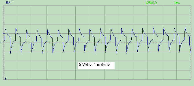
Next I decided that I need a crankshaft position sensor (CKP) signal, which has some number of pulses per revolution of the crankshaft. To test whether the CKP signal would be enough to get the tach and speedometer working I created a breadboard with a voltage to frequency converter. (Microchip TC9402) I tied the breadboard output signal (a square wave that I can vary from 100 Hz to 10 KHz) through a 0.1uF AC coupling capacitor to the PCM input pin that used to receive a signal from the now missing magnetic CKP sensor. The resulting waveform is shown below.
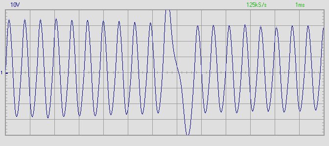
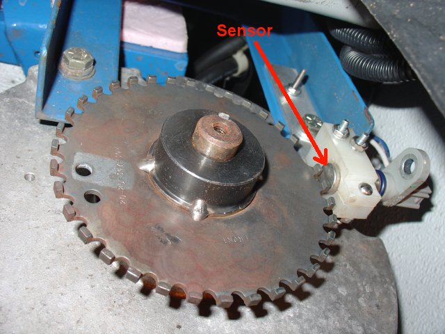
The next step was to try to get the engine RPM signal for the tachometer. I knew that I needed a CKP signal that follows motor RPM, but there was no way to mount the original sensor to detect the holes in the flywheel. Instead I purchased a crankshaft "pulse wheel" from the Ford dealership. (Ford part number F63Z 12A227 AB - around $35) This pulse wheel is used for the same purpose on other Ford engines (specifically the Contour version of the Zetec engine) and provides the correct number of pulses per revolution (35). I also purchased from Ford the magnetic sensor that goes with the pulse wheel. (Ford part number 5L8Z 6C315 AA - around $51) With an appropriately sized keyed sprocket from Grainger, the help of a local EV guy with a lathe, and a bit of tack welding I was able to mount the wheel on the auxilary shaft of my DC motor (the end opposite the transaxle) and then fabricate a bracket to hold the sensor in close proximity.
With this in place I measured the signal from the sensor to the PCM. It looks very good, as seen below.
With this connected to the PCM I saw the same behavior as with the breadboard - the tachometer briefly goes up but then quickly drops back to zero. I checked the connections and scratched my head, and gave up for a while. A couple of days later I realized that I hadn't paid attention to the polarity in connecting the sensor wires to the PCM. Since it was a two wire sensor I figured that it put out pulses and the polarity wouldn't matter. But I found that by switching the polarity of the two wires from the sensor to the PCM the tachometer started working! Problem solved! So now I've got a working factory speedometer and tachometer without having to create any extra circuitry of my own.
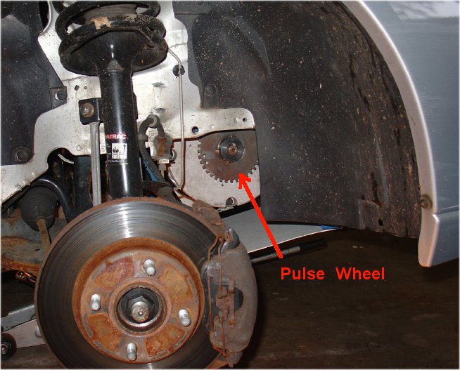
The pictures below show the pulse wheel mounted to the auxiliary shaft and the sensor mounted nearby. This is located behind the passenger side front wheel.
The movie below shows the speedometer and tachometer as I drive the car - working as they should.
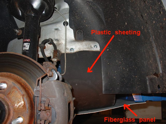
I installed plastic sheeting over the end of the motor (and a fiberglass panel below the motor) to prevent road spray from getting into the motor or on the pulse wheel. The picture below shows this.
Updated 17SEP2010